Electrical Transformer Circuit Diagram
Electrical Transformer Circuit Diagram Three-phase, also written as 3-phase or 3φ type supplies are used for electrical power generation, transmission, and distribution, as well as for all industrial uses. Three-phase supplies have many electrical advantages over using single-phase power. But when considering the use of 3-phase transformers we have to deal with three individual alternating voltages and currents differing in phase

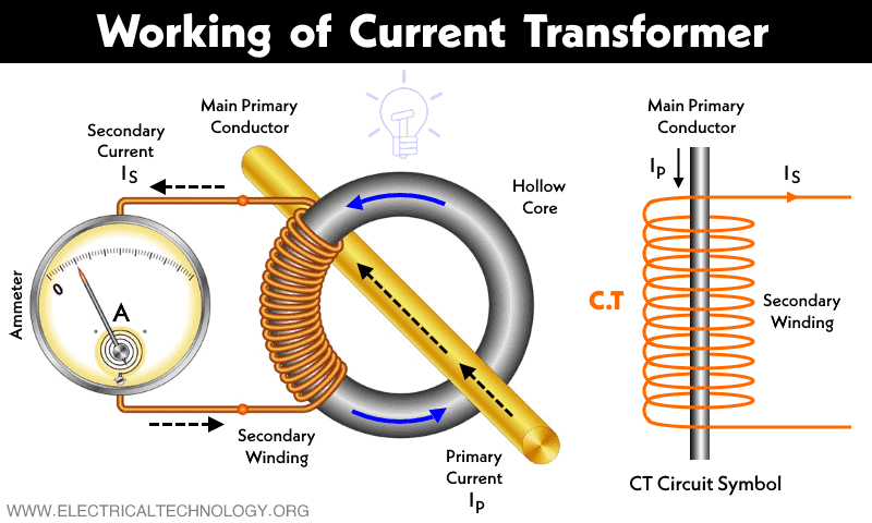
Learn about different types of transformers and their symbols and diagrams in electrical engineering. Find out how transformers work, what they are used for, and how to read transformer diagrams.
Basic Electronics Tutorials and Revision Circuit Diagram
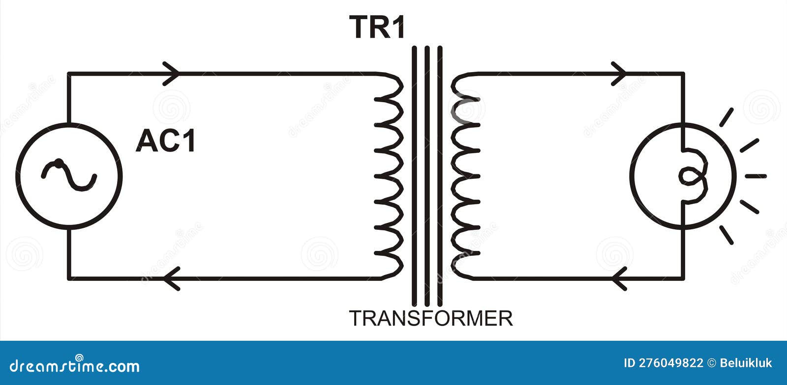
Transformer is a device that transfer electrical energy from one alternating-current circuit to another circuit or multiple circuits. Transformer works on the principle of electromagnetic induction. Transformers either increase AC voltage (Step-up transformer) or decreases AC voltage (Step-down transformer). According to the diagram below

Ultimately, circuit diagrams of transformers demonstrate one of the greatest aspects of electrical engineering: that pure science can be used to create practical solutions. They show us how abstract principles such as magnetism and induction can be applied in real-world applications, connecting us to the useful applications of electricity.
Definition, Types, Working Principle, Equations ... Circuit Diagram
Learn what is a transformer, how it works based on mutual induction, and its main components and functions. See the schematic diagram of a single phase transformer and its construction details.